Shortly after our arrival in north Florida, our friend Arne N7KA made us aware of the K7RT SK estate in nearby Brooksville that had a 100 ft Rohn-45G tower available. I hired Dan K1TO of A1 Tower Service (now retired) to dismantle and transport it to the new QTH.
I decided to use the ten 45G sections to put up two 50 ft towers. One holds stacked 9-element beams for 144 MHz and the second tower has single yagis for 50 and 222 MHz. In summer 2024, I added two 6m LVAs (large vertical array: a fixed stack of 4 x 3-el) pointing to the northeast on one tower and a second LVA pointing northwest on the other.
VHF DX in Florida is excellent, but it comes at a price: occasional hurricanes and frequent lightning. In an attempt to attain high reliability and integrity, I did commercial-grade tower installations, closely and carefully following the documentation in the Rohn catalog. The two structures are setup identically.
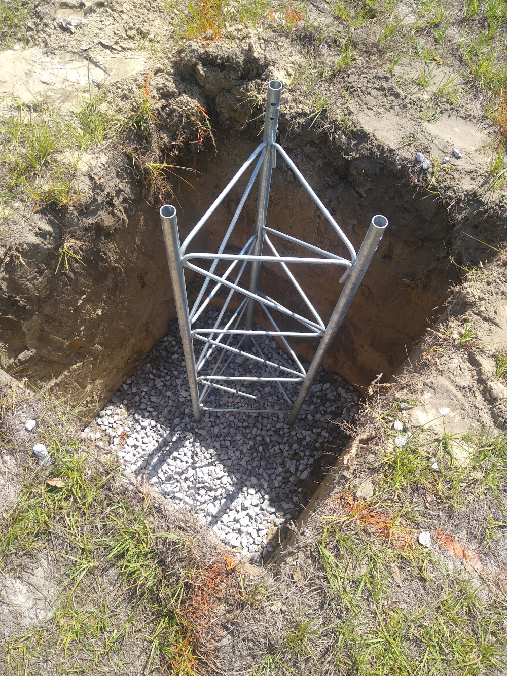
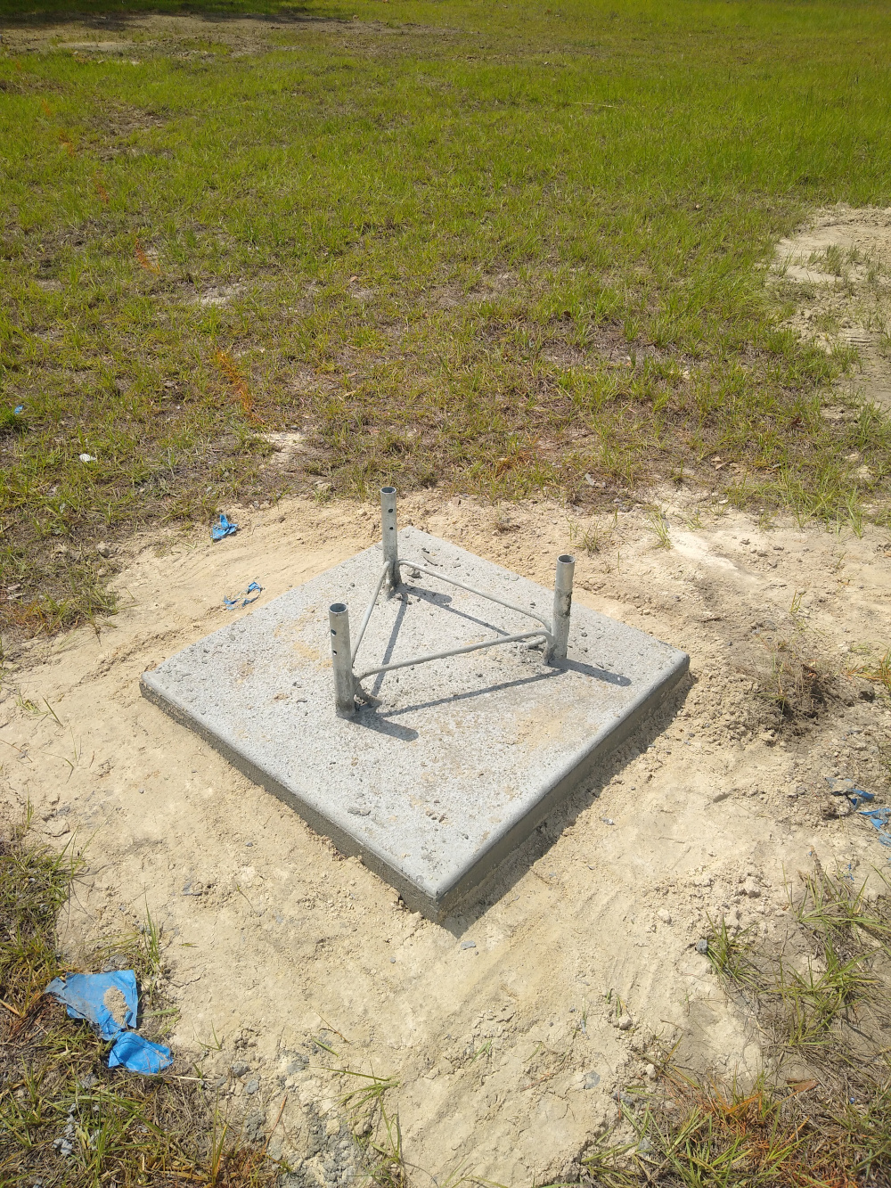
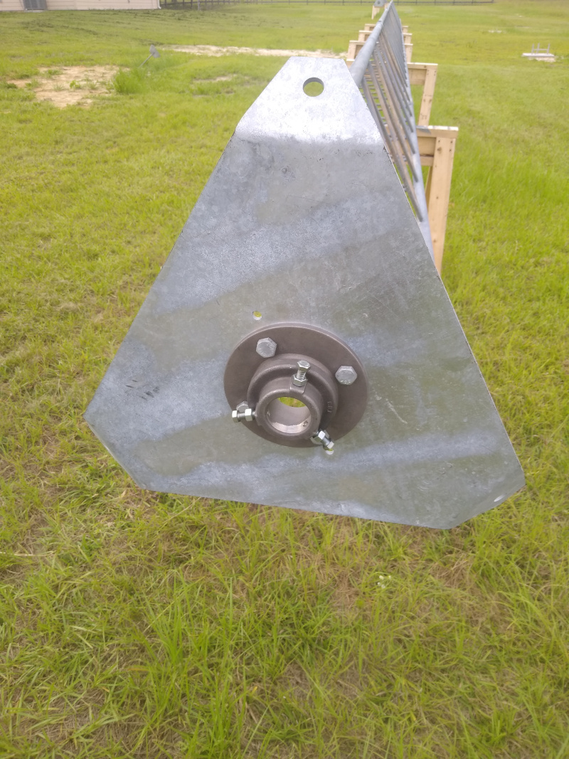
Each tower base is a brand-new 5 ft section of 45G that is placed in a 30 x 30 x 48 inch hole. The bottom of the hole is covered with gravel for drainage. The two bases are separated by about 135 ft and located 85 ft from the shack.
A single set of guys are spaced at 120 degrees and anchored at a 40 ft radial distance from the tower center. One tower uses 7 ft Rohn GAR30 rods with a single eyelet. The second has 7 ft Rohn GAC3455TOP rods with attached 5 hole equalizer plates that were generously donated by Art WA2LLN. I guyed to the center hole.
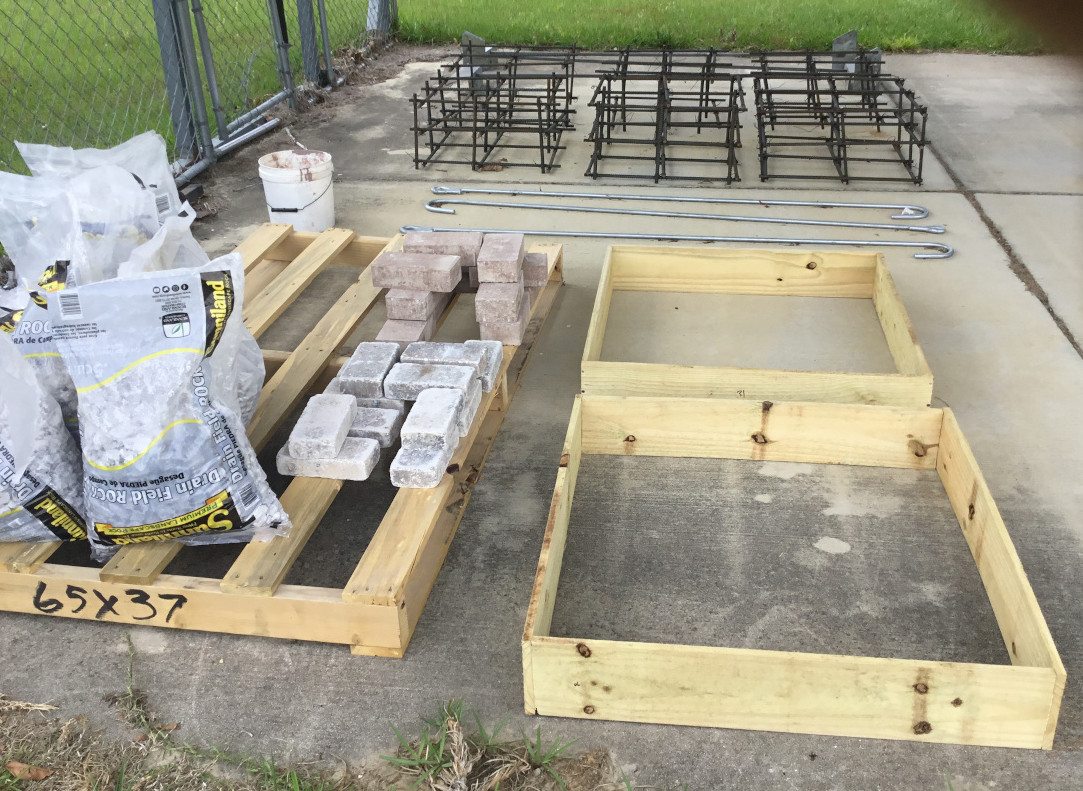
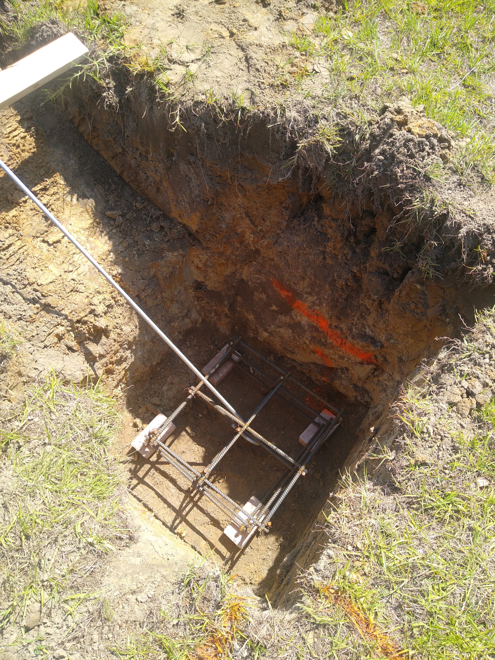
The ends of the anchor rods are embedded in 36 x 36 x 18 in blocks of concrete reinforced with 1/2 inch rebar, buried at 4 ft. This is sometimes called a "dead man" anchor. I ordered the rebar cut to individual lengths from Metals Depot and assembled the six cages myself using saddle ties. A few bricks keep the cages from contacting the dirt floor of the hole. The photos show the various components prior to and during installation.
|
|
|
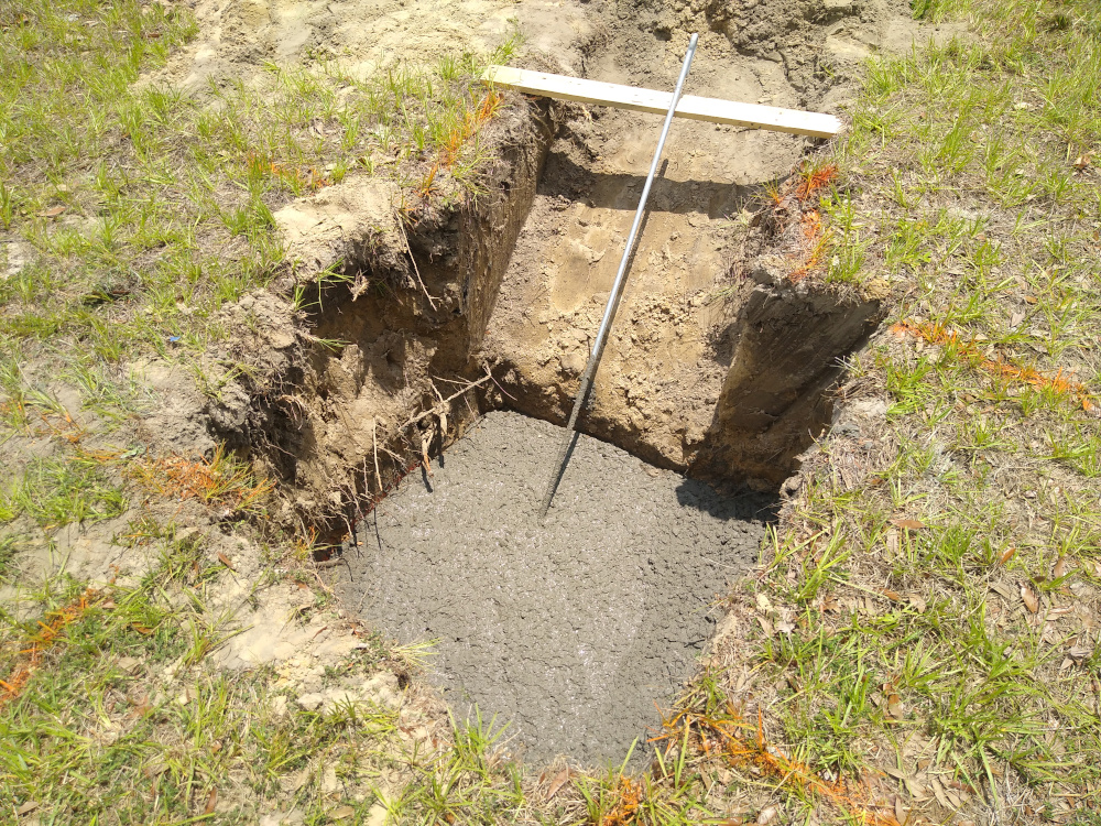
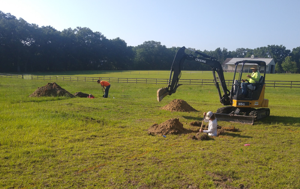
A contractor had all the holes neatly dug and ready for the concrete pour in just a couple of hours. I was happy to hand over this part of the project to the pros. Here is a video and second one showing the concrete going into the anchor holes. Each block of concrete weighs roughly one ton.
|
|
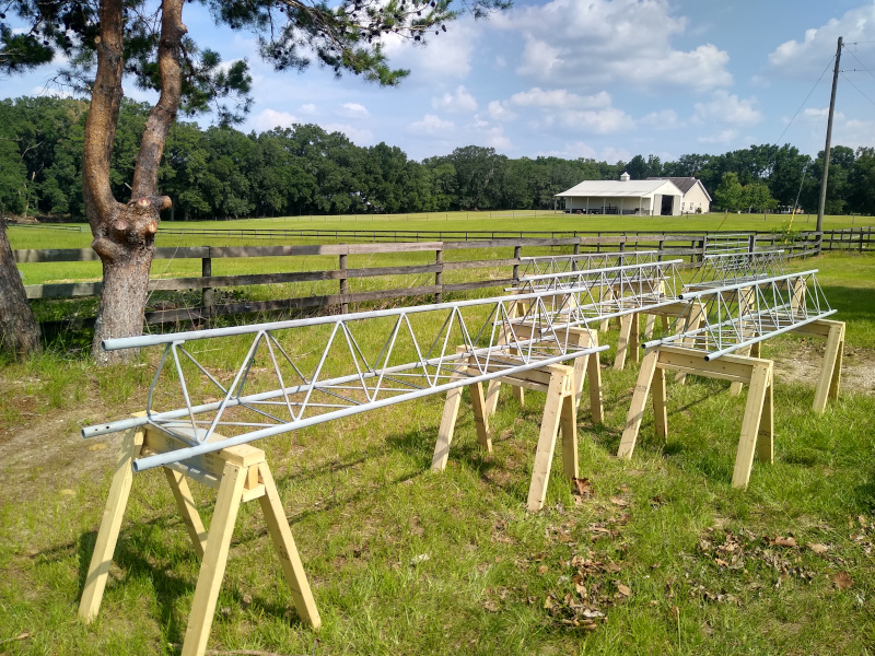
The tower sections were all individually cleaned with compressed air and touched-up as needed with a wire brush and cold galvanizing compound spray. I built 10 sawhorses to keep the sections up off the grass and dirt, which made them easier to work on.
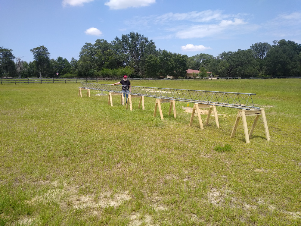
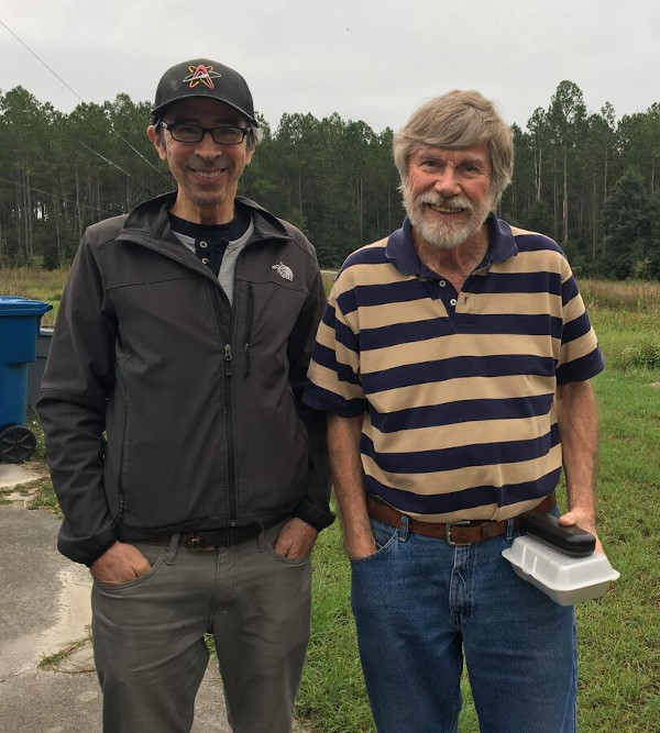
Assembly then took place horizontally with the able assistance of my neighbor Hal WA4QLA. We needed slight leg bending provided by cargo straps and plenty of hammering at almost every joint, but eventually all the sections were bolted together. The photo on the right shows Hal standing next to one of the completed towers.
|
|
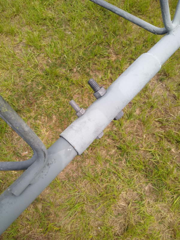
For reasons not clear to us, each joint in the Rohn design has two different bolt sizes. The only explanation we've been able to come up with is that use of a smaller bolt saves some component cost. The entire vertical load of the tower is maintained by the shear strength of these bolts and whatever static friction exists at the leg couplings.
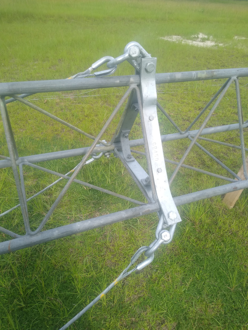
A Rohn GA45GD bracket assembly is installed at the 42 ft level, ie. 8 ft below the top of the tower. WA4QLA donated 1/4 inch EHS cable for guying. Guys are attached to the bracket with Big Grip preforms, 3/8 inch thimbles, and 5/8 inch galvanized shackles. At the top of the tower is a Rohn BPL45G plate that holds a heavy-duty TB-3 thrust bearing for the mast. All the hardware was purchased new from 3Star and increased the cost of the project significantly.
|
|
The VHF antennas are positioned with Yaesu G-450A light duty rotors. Following the instruction manual, the rotor is located about 40 inches below the thrust bearing, bolted on a Rohn AS455G mounting plate. The plates are pre-drilled for HyGain rotors, not Yaesu. Ron KM4SYT helped me out in his machine shop by drilling holes on each platform for the Japanese metric hardware.
The 5-section towers were lifted into place by B & C Crane Services in Gainesville, Florida. A harness is looped at the top, the crane hoists the tower vertical then carefully swings it into place just above the base (see video). Our very skilled crane operator Curtis was able to align the bottom section with enough precision to allow the ground crew (me, WA4QLA, KM4SYT, and Steve W4IT) to install the last set of bolts. Curtis then took tension off the harness and disengaged it from the tower without the need for any climbing. Both towers were bolted to the bases in under an hour.
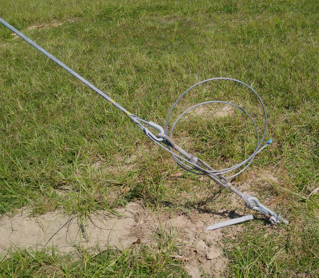
A second set of Big Grips and eye-to-jaw turnbuckles attach the guys to the anchors at ground level. A Loos PT-2 tensiometer allows straightforward adjustment of the turnbuckles. Each turnbuckle is tightened to reach 10 percent capacity of the 1/4 inch EHS cable, corresponding to about 600 lbs of tension.
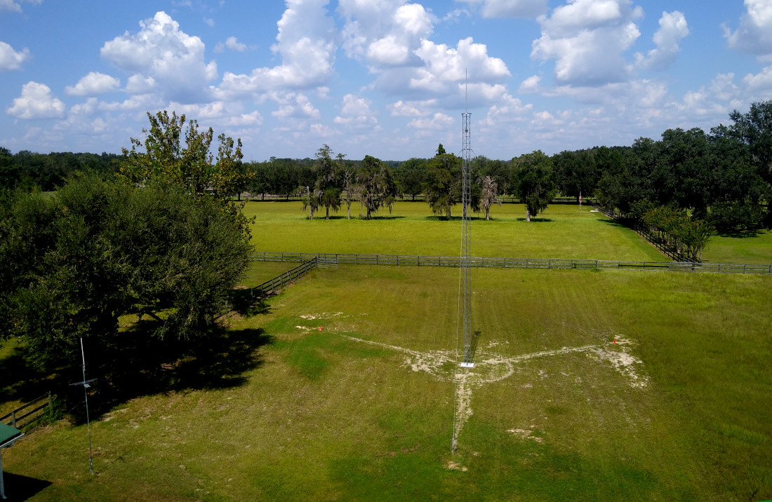
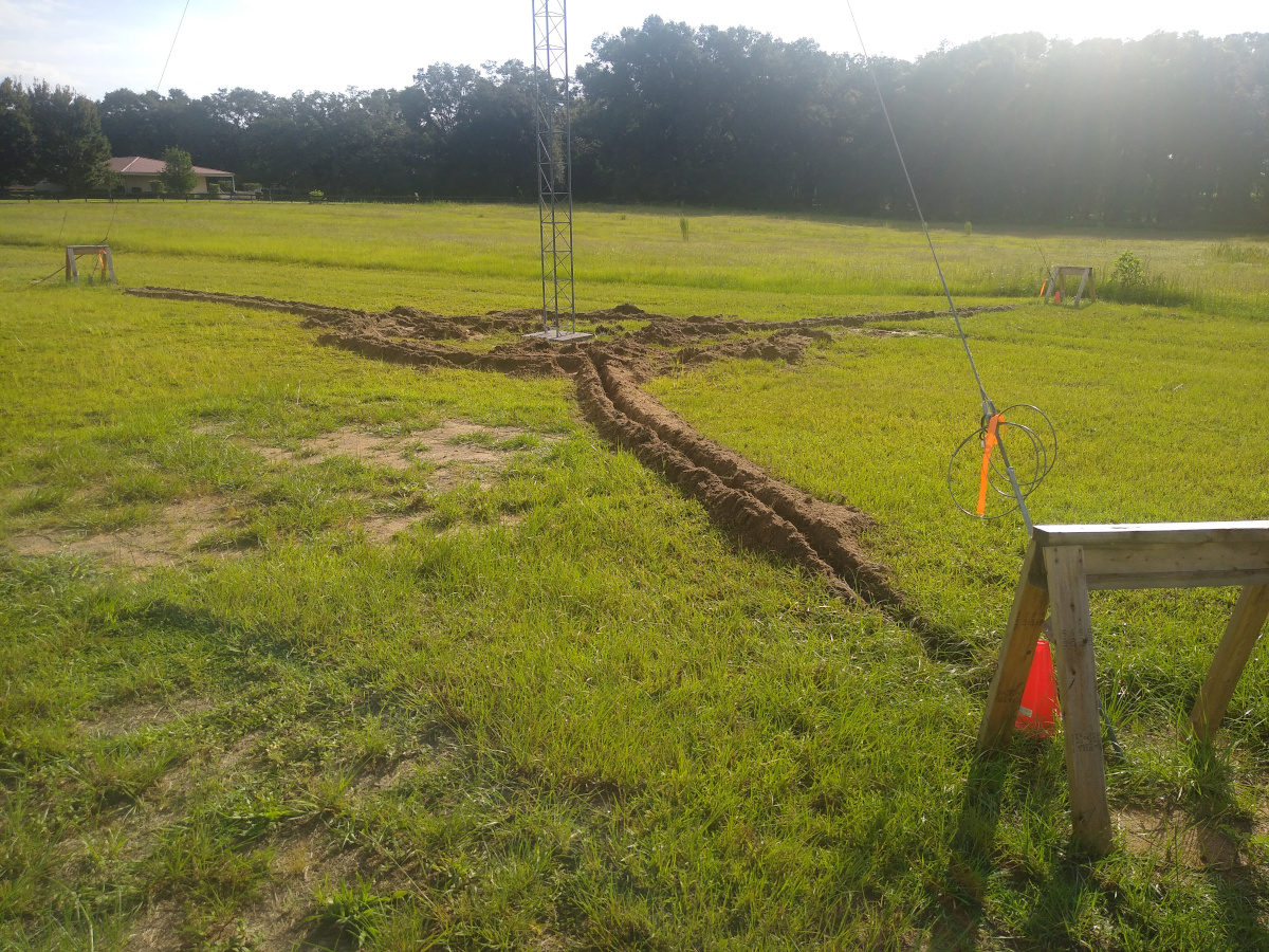
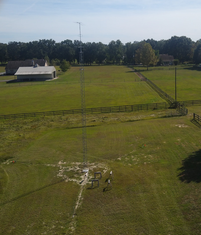
This is my first experience with guyed Rohn 45 and I have been unable to detect any motion or swaying when climbing it. The right photo below is the view looking to the north at a height of about 42 feet where the guy bracket is attached. You can clearly see the filled trenches for the grounding radials of the second tower.
|
|
Grounding
Lightning hits are probably inevitable, so a ground system attempts to dissipate strike energy in the earth in immediate proximity to the tower. My layout followed the guidance in the ARRL Grounding and Bonding handbook by N0AX. Each tower leg is connected to a buried 6 gauge bare copper wire to form a radial that extends 40 ft to the guy anchor. Depth is 8-12 inches below the surface.
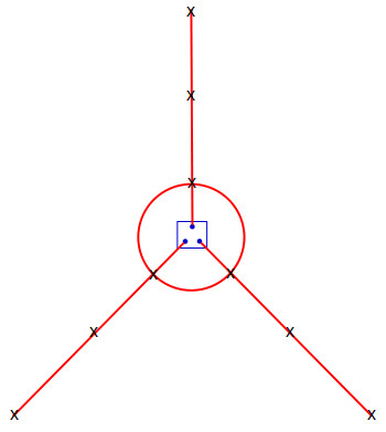
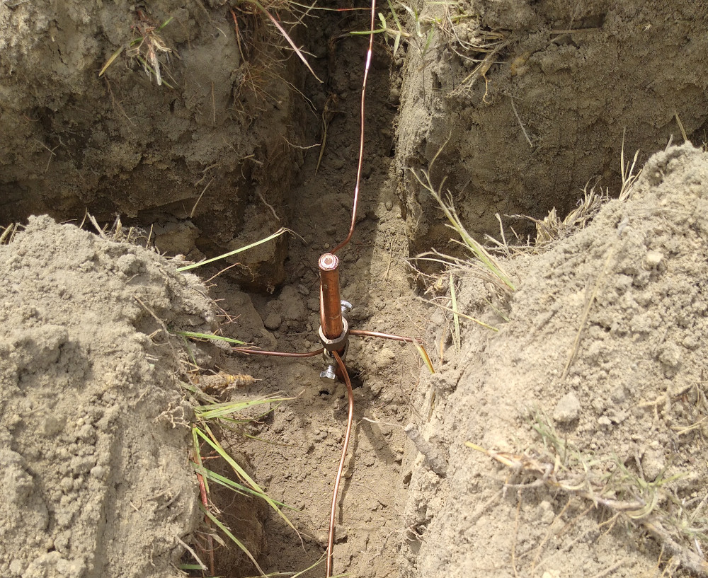
The three radials are electrically connected by an 18 ft diameter wire ring buried at the same depth. 8 ft ground rods are located at each intersection, which separates the inner rods by the desired direct path of about 16 ft. A ground rod is also placed at the far end of the radial, adjacent to the guy anchor and connected to the EHS cable. Another ground rod is clamped to the radial midway between the ring and anchor. There are 9 ground rods per tower with positions marked with an X in the layout sketch below (not to scale).
|
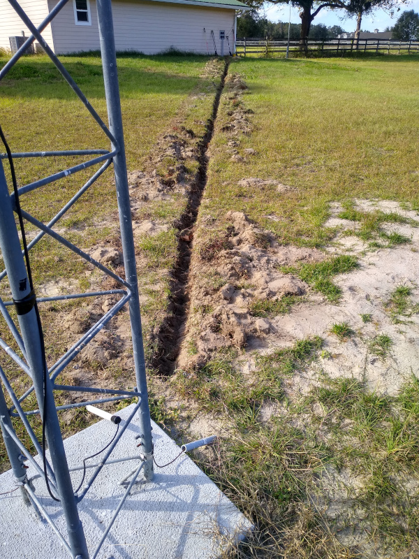
I toyed with the idea of digging the trenches myself by hand, but gave up after 15 minutes in the hot summer sun. A local electrical contractor had the needed motorized trenching tool along with some assistants who made short work of the job. Unlike me, they don't work for free.
|
|
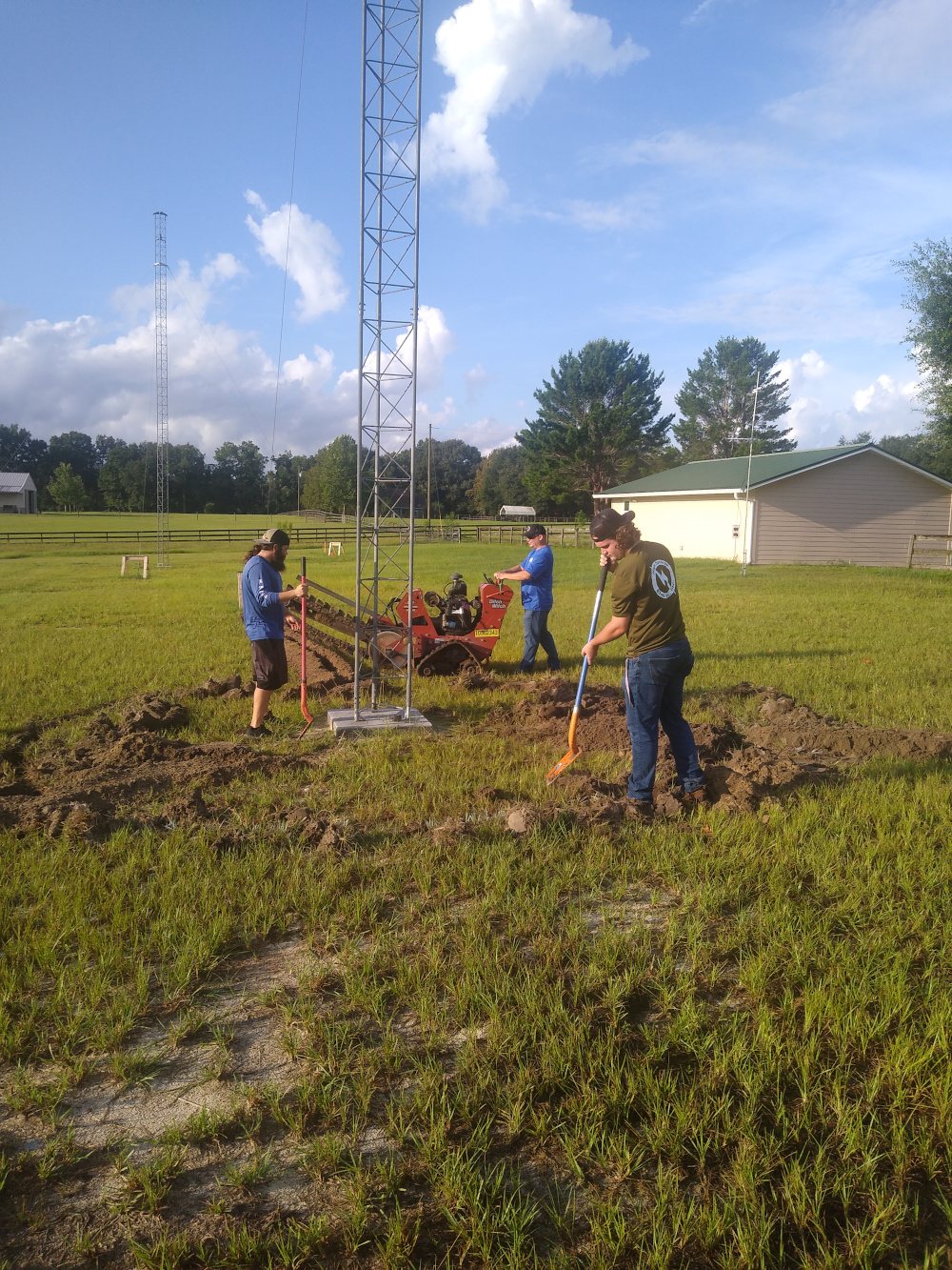
I used a Bosch hammer drill with an appropriate adapter to drive in the ground rods. I had long anticipated this step and made sure there was a power outlet installed on the outside back wall of the shack. Even with the drill, the last 4 feet proved to be quite stubborn. Sinking all 18 rods consumed the better part of a day.
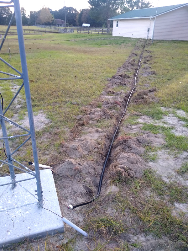
Connecting the ground wire was complicated by the presence of several fire ant colonies in the trenches. I incurred many nasty bites during the process, but eventually got all the radials wired to the rods. It is well known that when copper is clamped directly to galvanized tower legs, oxidation will occur. I used specialty clamps with steel shims available from DX Engineering. At the far end of each radial, the wire emerges from the earth in a conduit and gets clamped to the guy anchor. There are purpose-built clamps for this but they are ridiculously expensive; I was able to get a decent deal on six from Electrical Parts. Refilling the trenches with all that excavated dirt was also much harder than I expected so I was glad to get the manual labor over with.
|
|
The towers are far enough from the shack and each other that there is no benefit to tying their grounds together or connecting to the station perimeter ground. The inductance of these relatively long wire runs would generate huge potentials in a fast-rising lightning strike. This is explained well in the ARRL grounding book.
Antennas
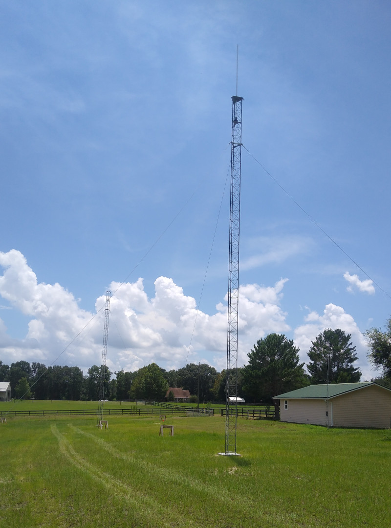
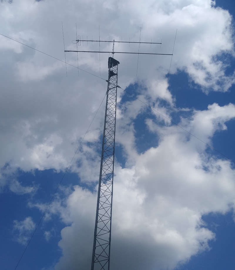
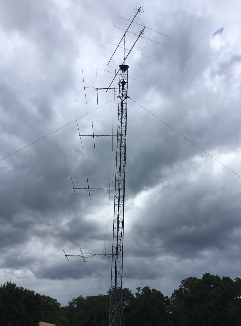
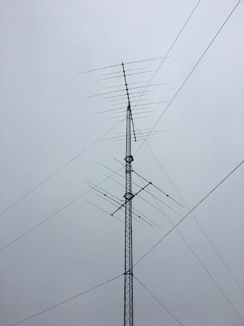
The masts are lengths of 1.5 in galvanized pipe (OD 1.9 in) that were obtained from Metals Depot. These masts are heavy and not cheap, but I was aiming for hurricane survival. An M2 6M5X 50 MHz yagi was originally located on the north tower at about 53 ft. In November 2024, it was replaced by a 6-element 6M6DX purchased directly from Antennas-Amplifiers in Serbia. At the top of the mast at a height just under 60 ft is an 11-element InnovAntennas LFA (4.7m boom length) for 222 MHz (left photo, below). In April 2025 it was swapped out for a 222DX12AP 12-element yagi from Antennas-Amplifiers.
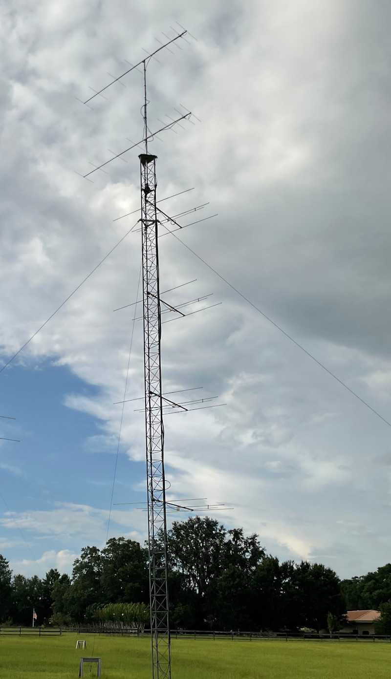
The south tower holds stacked 9-element beams for 144 MHz (M2 2M9SSB) at a vertical spacing of 9 ft 6 in (right photo, below). The height of the top yagi is about 62 ft. Because alignment is critical, I assembled antennas and feedlines on the mast at ground level. Phasing lines are from ABR Industries and the 2-port power divider is from Directive Systems.
|
|
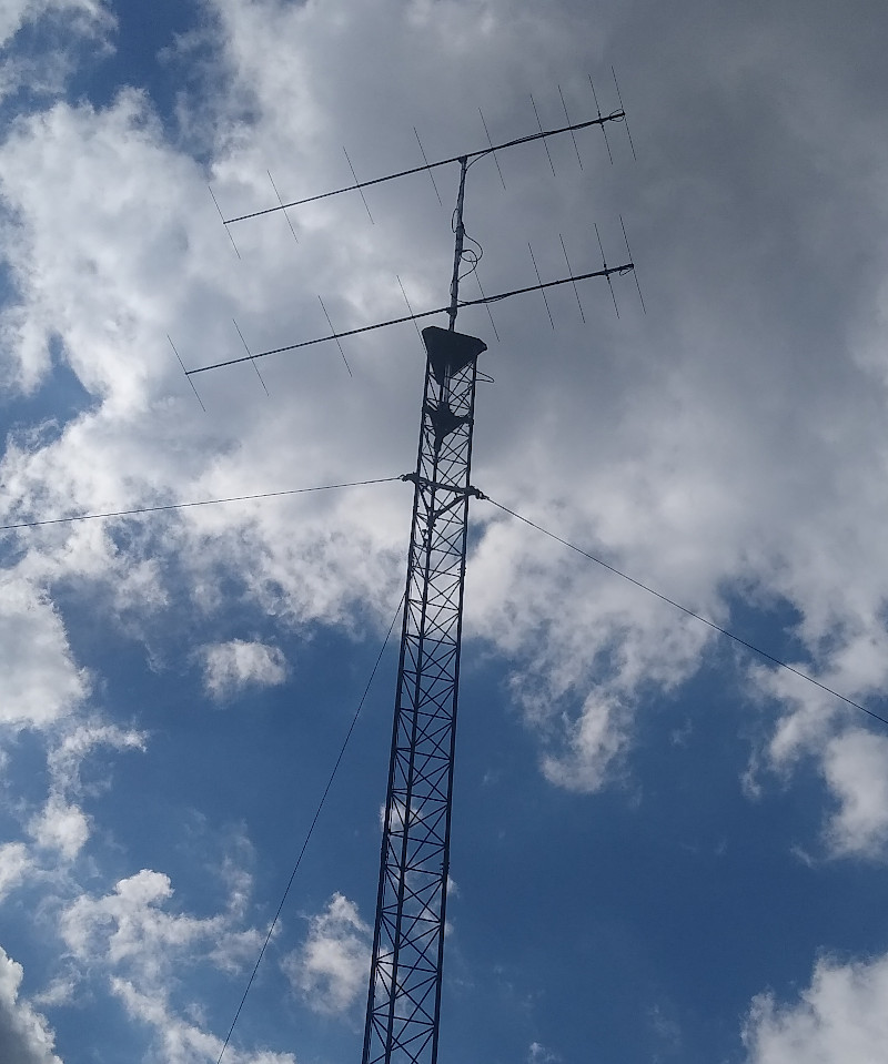
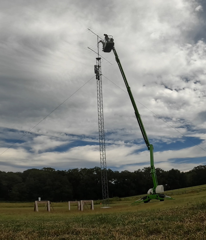
The mast was already installed on the north tower when the crane lifted it into place, so I hired a bucket truck crew to clamp on the the 6m yagi followed by the 222 MHz LFA. The 144 MHz mast/antenna assembly was heavy and awkward, but the bucket crew was able to hold it, then raise it to the top of the tower. The left photo below shows me on the tower guiding the bottom of the mast into the rotor clamps. I then climbed to the top of the tower and tightened the bolts on the thrust bearing. I'm wearing a DBI-Sala ExoFit climbing harness, AFP dual fall arrest lanyard, waist-mounted positioning lanyard, engineer boots, and hard hat. Everything was under the watchful eye of Steve W4IT on the ground who provided fine-tuning of the azimuthal alignment. The right photo shows the stacked 2M9SSB yagis in place as seen from the top of the north tower. The fences in the distance separate our neighbors' horse pastures.
|
|
When the 2m yagis were first installed, I equipped them with brand-new, custom phasing lines from M2. Unfortunately, the N-connectors on these coaxial cables were defective and failed after about 20 hours running high power. Female connectors on the 2-way power divider were also damaged. These problems were intermittent, time-consuming, and expensive to track down. I had a contractor with a bucket truck on site three different times! Steve N2CEI of Downeast Microwave eventually helped sort out the issues and was able to repair the power divider. Current phasing cables are 10 ft lengths of ABR-400.
CAUTION: I have experienced a variety of catastrophic failures when running N-connectors at high power. This sometimes manifests as an excessively flared inner pin receptacle on the female connector leading to an intermittent contact. It may occur due to local RF heating as a result of cheap materials and/or defective manufacturing. Use of high quality cables and connectors is crucial in QRO applications.
My VHF antennas were originally setup at the former QTH in DM65 and moved with us to Florida. There has been considerable, ongoing difficulty dealing with intermittent high VSWR on the 6M5X 6-m yagi. I have some observations about using the segmented element design in a permanent installation.
Large Vertical Array (LVA) for 6-meters
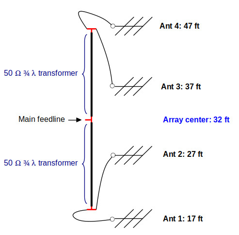
In 2024, I purchased eight 3-element 50 MHz yagis from W5ZN that were originally sold by Directive Systems (Model DSE3-50). After substantial refurbishing, I used these to build two fixed-direction four-stack arrays with individual antennas mounted at heights of 17, 27, 37, and 47 feet. This puts the center of the array at 32 feet. The north stack points northwest at approximately 330 degrees (direction of JA, left photo) and the south stack looks northeast at about 45 degrees (direction of EU, right photo). These azimuth angles are not critical and were selected primarily to avoid interfering with the guy wires.
|
|
The LVA is attractive because gain is comparable to a mid-sized yagi but with a much broader radiation pattern. Using xnec2c to model the LVA indicates gain close to the 7-element M2 6M7JHV with a 3 dB azimuthal beamwidth of ± 32.5 degrees. This can be advantageous when working meteor scatter or in a contest situation, as different geographic regions can be quickly accessed with the flip of a rotary switch.
Marshall K5QE gave a detailed presentation at the 2019 Pacific Northwest VHF Society Conference describing the LVAs installed at his contest station. The 3-element yagis he uses were designed by W5UC with dimensions very similar to the DSE3-50. Instead of 1/4 wave impedance transformer cables, I use 3/4 wavelength 7/8 inch hardline. I built the transformer cables to have a length very close to 13 feet accounting for the velocity factor and N-connectors; these longer transformers reduce the length of the phasing cables. The absolute length of the four phasing cables is not critical provided they are precisely matched. Each of my phasing lines is 13 feet of ABR-400 with male N-connectors that are cut at the factory with a 1-mm tolerance. A diagram of the setup is here.
The LVA has six precision lengths of coaxial cable (four phasing lines, two 3/4 wavelength impedance transformers), three T-connectors, and 13 individual cable connections that must be weatherproofed. For the primary feedline I run 35 feet of FSJ4-50B from the center of the array to the base of the tower where it connects to 85 feet of buried 1/2 inch hardline (Konnect RF) that routes to the shack.
I checked the response of each antenna individually with the NanoVNA. In each case, minimum VSWR was found to be above 51 MHz. At the FT8 frequency of 50.313 MHz, I saw a consistent VSWR of around 1.4:1. Adjusting the T-match had almost no effect and that was the extent of my tuning efforts.
The three 6m antennas (rotatable yagi + two LVAs) are on separate feedlines with individual lightning arrestors. A fail-safe, 3-position antenna switch is at the operating position.
Notes on installation: The 3-element yagis can be installed by a single tower climber. Firmly attach the four mounting brackets to the tower legs at the appropriate 10 ft spacings. On the ground, tie a rope to the antenna boom between the driven element and reflector. The phasing cable is already attached and secured to the boom. On the tower, use the rope to pull the antenna up to the bracket, but run the free end of the rope over the tower rung above the bracket and tie it there when the antenna is in position. This will provide some leverage to hold the antenna horizontal while the end of the boom is slid into the two U-bolts. You will need a good positioning lanyard on your harness so you can lean away from the tower with two free hands. Start with the top antenna and work your way down.
Feedlines
I acquired several hundred feet of 7/8 inch LDF5-50A and EC5-50A hardline from Dave N9HF in Ormond Beach. This cable was used to build low-loss feedlines for the 144 and 222 MHz stations. The 6m antennas are fed with 7/8 inch heliax, FSJ4-50B 1/2 inch flexible heliax, and buried runs of 1/2 inch hardline purchased from Konnect RF. Connectors were obtained from Steve at N4SVC, Marshall K5QE, rfparts.com, and eBay. The short transition lengths are ABR-400 from ABR Industries. The Yaesu rotator control cables are buried in PVC conduit. Each cable trench runs about 85 ft from the cable feedthrough wall panel to the base of the tower.
|
|