For a typical residential setup, you might as well forget about using 120 VAC to power
a 4 kW power supply. There's simply too much current draw at wall plug voltage. Power from
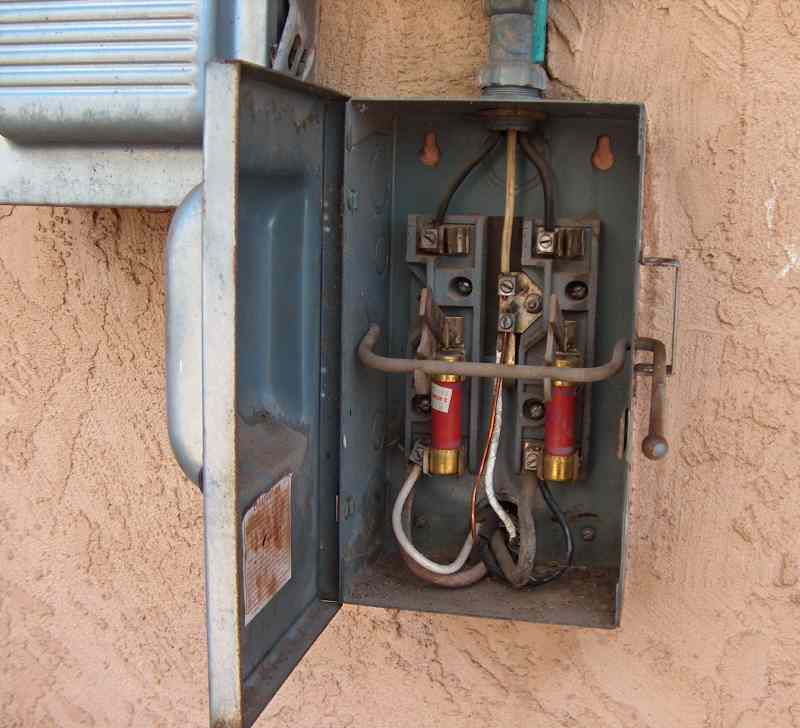
my utility company connects out at the garage, where
the washer and dryer are located. Accessing 220 VAC for the amplifier necessitated a 40' run of
8-gauge Romex under the house to the operating position. I put the amplifier service line in parallel
with the dryer so it shares the same fuses, just past the power shutoff switch outside the house.
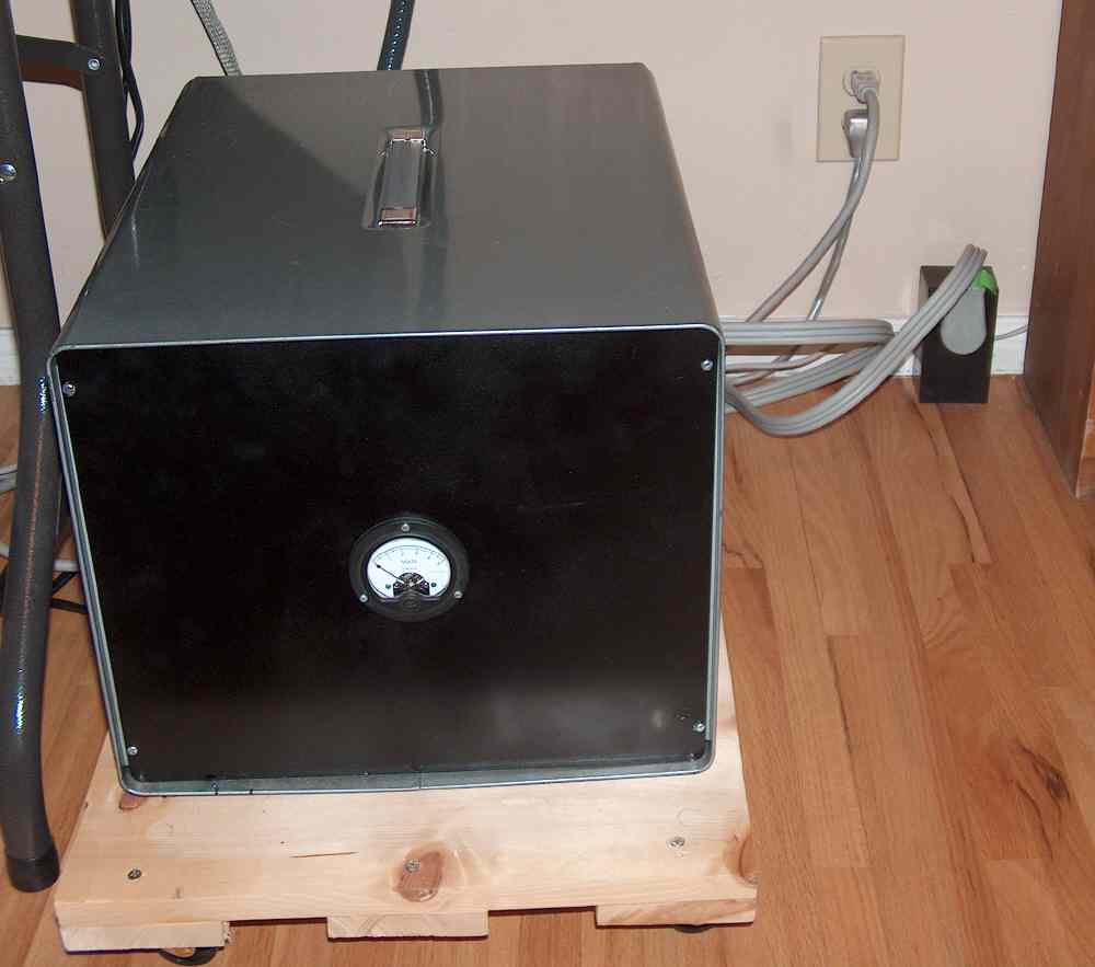
I drilled a hole in the floor and installed a three-phase dryer plug outlet by the baseboard. The power supply connects
to it with dryer cord as can be seen here. The enclosure was obtained from a local surplus house
for 20 bucks. The main transformer is so heavy that I had to build a roller dolly to move the thing around.
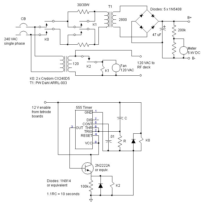
The power supply is adapted from the design found in just about any ARRL handbook. Click
here for
the schematic diagram.
A PW Dahl ARRL-003 transformer
provides close to 4 kV at 1.5 amps, which is more than enough to feed
the anode of the GS23B when running the legal limit. A full-wave bridge rectifier is implemented with a string of
five 1N5408 diodes in each leg, because individial diodes do not have sufficient PIV to handle the operating voltage.
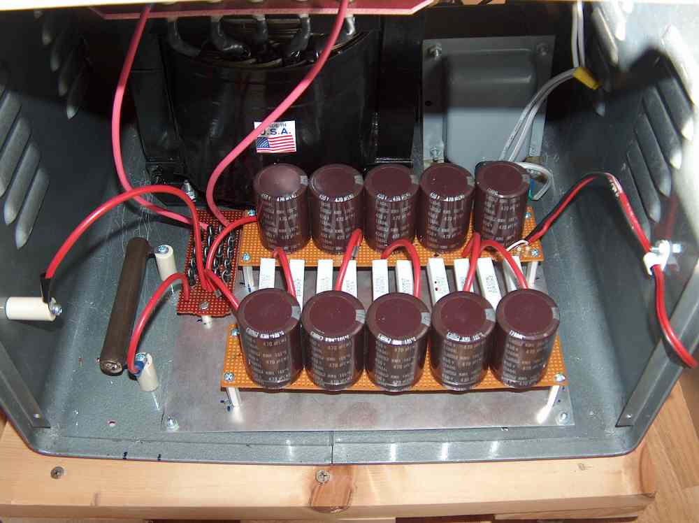
A single, big filter capacitor for 4 kV is expensive, so I built one by stacking
10 x 470 uF 450 V electrolytics (All-Electronics) in series
as shown here. Voltage is shared equally between the capacitors
via a divider network based on 20k cement
resistors (Mouser). This
resistor chain also bleeds down the capacitor charge.
This is an inexpensive way to filter a big supply but requires a lot of wiring and soldering. Note that
the resistor stack is hanging out in free space between the perfboards so that air convection can aid in the removal
of nearly 80 Watts of heat being generated there. In the lower left, a 50 ohm 50 Watt glitch resistor awaits
connection to the B+ line coming from the rf deck. The B- return is NOT at ground potential
in this design and is insulated from the chassis
with a ceramic standoff. Visible next to the big transformer in the upper right is a 240/120 stepdown transformer
to provide unrectified AC to the rf deck.
In the first several hundred hours of operation, the power supply experienced three separate
failures in the filter network. It's not clear if the cause
was individual electrolytic capacitors or cement resisitors. After each incident, however, the ohmmeter revealed
that at least one cement resistor had opened. I decided to abandon the elegant divider network for the more
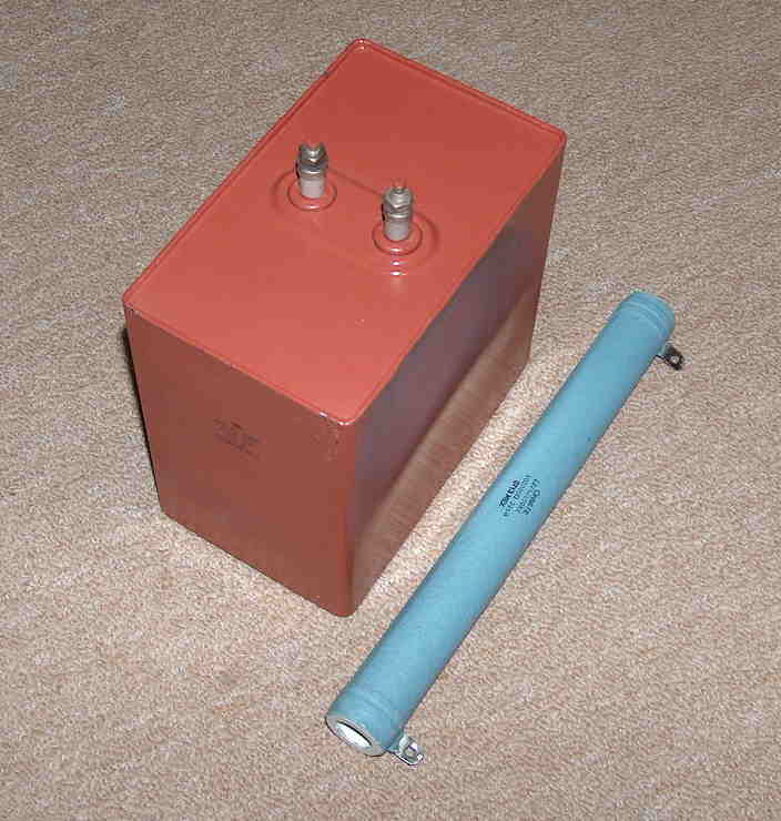
expensive brute-force solution that uses one large capacitor and power resistor shown
here. The 40 uF capacitor is Russian military surplus that is available from several
different suppliers on ebay. The power resistor is a standard ceramic 225 Watt 100-k from Ohmite. Their placement
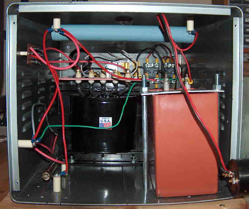
in the cabinet can be seen here. The bridge rectifier has been relocated to the sidewall
and the capacitor held in place with a homemade bracket. The power resistor dissipates about 160 Watts
at 4 kV, which makes the top of the cabinet where it sits way too hot to touch! This filter
modification added about $200 to the cost of the project.
The power supply is entirely under the control of the rf deck -- specifically the tetrode boards. That's why
there is no switch on the front of the power supply cabinet. There is a 3-phase breaker switch on the back panel,
but it is out of the way
so it can't be accidentally tripped. When it's time to use the amplifier, the blower is turned on at the rf deck
along with the filament heater. This starts a 4 minute timer on the tetrode boards.
Four minutes later, after the filament is warm,
the tetrode board sends an enable signal to the high voltage power supply, which connects 220 VAC to the big
transformer primary through two Crydom CX240D5R solid-state
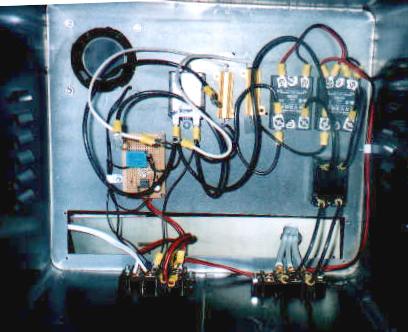
relays in the supply cabinet. Click here
to look at the inside of the cabinet with
the transformers not yet in place. The relays are visible on the right back wall. When the
supply is enabled, primary current must pass through two 30 ohm power resistors located adjacent to the
relays. A second delay circuit, implemented
with a 555-timer on the small circuit board in the lower left, keeps the power resistors inline for about 10 seconds.
This is a step-start to limit the initial current surge into the discharged filter
capacitor, thereby easing the jolt to the transformer.
After this delay, a small low-power relay (blue cube on circuit board) activates a large DPDT relay (center left),
which bypasses the power resistors to connect 220 VAC directly to the main supply transformer. At this point, the tube
is ready to make power. Note the circular fan (upper left) that begins moving air through the cabinet when the
transformer primary
goes hot.
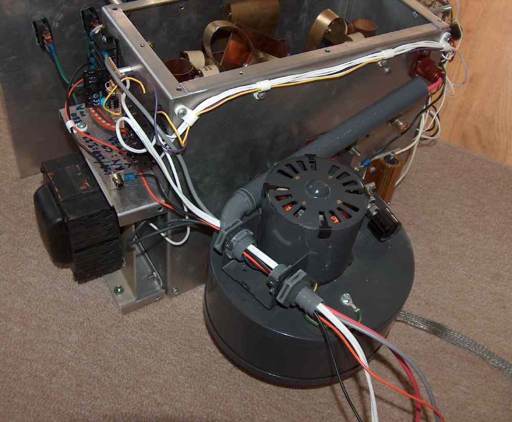
For safety, all connections between the rf deck and high-voltage supply are housed in flexible conduit.
There are six wires in the conduit
as follows: plate in (B+), plate return (B-), single phase 120 VAC (two wires), and the 12 Vdc enable (signal
and return at common chassis ground).
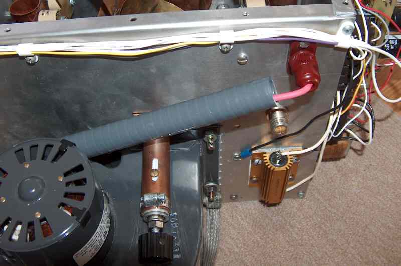
The conduit connects to a plastic nipple at the blower as can be seen here,
with the cover removed to reveal the wiring.
The single high voltage B+ line leaves the blower box and
continues up to the Millen connector in a second short section of conduit. You can
see that the
load capacitor tuning knob is uncomfortably close to this line...even though the high voltage line is doubly
insulated, I always use extreme care (i.e. I'm nervous) when making adjustments to this capacitor.
As a final important safety feature, the rf deck chassis is connected to the power supply chassis and ultimately earth ground of the
220 VAC service line with a robust, low inductance, tinned copper strap. This prevents either chassis from
quickly surging to high-voltage potential in the event of an accidental short.
Holes in the power supply enclosure were made using a drill, a nibbling tool, and hand files. This took a lot of time,
was hard work, and gave marginal results. It would have been smarter to buy or borrow a chassis punch kit or
have a machinist make these holes.
Part I-b: RF deck construction
WB2FKO homepage