The chassis was built with sheet metal from the W6PO package that had been sold by
K3IWK (SK). Following the KD5HIO writeup, the height of the tube mounting
platform must be reduced to accomodate the GS23B. It should be noted that this is not a kit -- it's a collection of
properly sized and matched sheet metal that will let you build a chassis. A lot of drilling and
hole cutting is required.
I was fortunate to have KD5HIO put together my tube socket. This is probably the most difficult
aspect of the construction and I escaped this chore by having it done for me.
It's a good bet that I would not have attempted
the GS23B amplifier if the socket hadn't been dropped in my lap by the guy who had already built one. You can read about
construction of this particular socket here. The critical issue
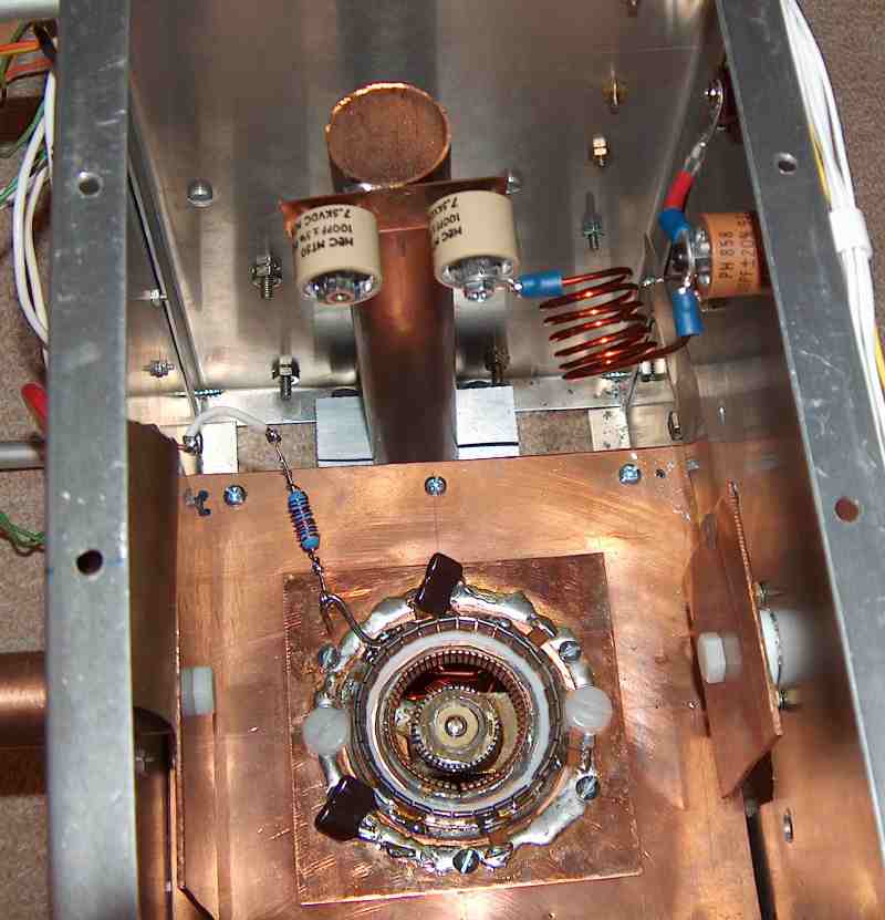
for a VHF tetrode is bypassing the screen ring to ground with the minimal possible inductance. Click
here to see mine as installed in the chassis. RF bypass is accomplished by a parallel combination
of chip capacitors (attached by resistance soldering) and silver micas. KD5HIO believes the simple
silver mica caps have sufficiently low
inductance to work at 144 MHz, so the chip capacitors are an over-design for this application.
---------------------------------------------------------------------------------------------
Update Fall 2024: While troubleshooting the amplifier, I had to remove and then resinstall the tetrode for the first time since construction was completed almost 20 years ago. The flexing stress on the socket caused the delicate chip capacitor joints to break or partially break off from the screen collet.
Chasing down this problem proved to be difficult. Without the chip capacitors, there were still two radial 1.5 nF mica capacitors to bypass the screen to ground. The DC currents and voltages remained at their correct values, but the amplifier simply could not be tuned to produce any output power. The presence of several non-functioning capacitors on the screen was evidently introducing too much stray reactance. Upon disassembly, it was found that all the 470 pF chip capacitors and one of the 1.5 nF radial capacitors had failed or was broken.
The design specifies a bypass capacitance of just under 3 nF. I removed all the existing capacitors and installed two new 1.5 nF 1 kV radial mica capacitors. The copper base flange is a very effective heat sink, but I do not have the equipment or experience to do resistance soldering as in the original construction. At the suggestion of WA4GPM, a hot plate raises the temperature of the flange to just below the solder melting point. A soldering iron can then be used for local heating to attach the radial leads. This let me keep the leads lengths under 2 mm, minimizing inductance.
With the refurbished socket, I was able to tune and operate the amplifier at the 500W power level. As the power approached 1 kW, however, one of the new bypass capacitors failed. Suspecting that it was a defective part, I replaced it, brought the power back up, at which point the other mica capacitor blew. There was never a pop, bang, or smoke, but the screen current trip caused immediate shutdown. It seems there was either too much current in the capacitors or excessive voltage across the screen due to the bypass inductance.
To address this, I replaced 2 x 1.5 nF with 4 x 680 pF 1 kV mica capacitors, which appears to have solved the problem. A picture of the rebuilt socket is here and yes, I should have arranged the capacitors more uniformly around the screen ring. Removing the socket to make these modifications is a fairly involved process. The amplifier must be partially disassembled to open the cathode compartment for screw access and to unsolder several connections.
---------------------------------------------------------------------------------------------
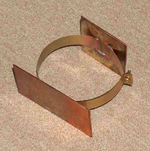
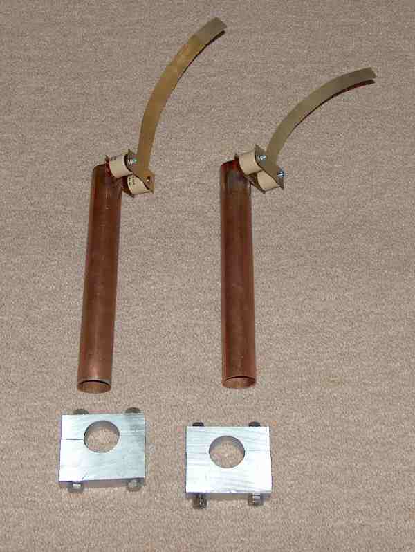
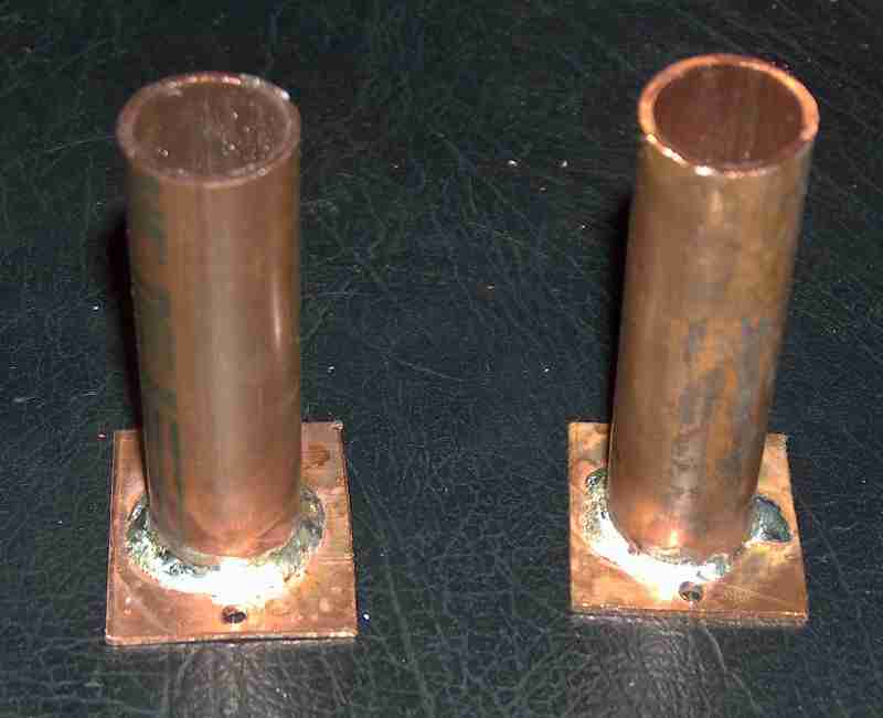
A lot of the rf deck fabrication requires soldering with a propane torch, which is how
I made the anode clamp, output
inductor assemblies, and mounts for the plate tune/load capacitor sliders.
Getting the
latter working well was tricky and I'm indebted to N5XZM for lots of help here. Click
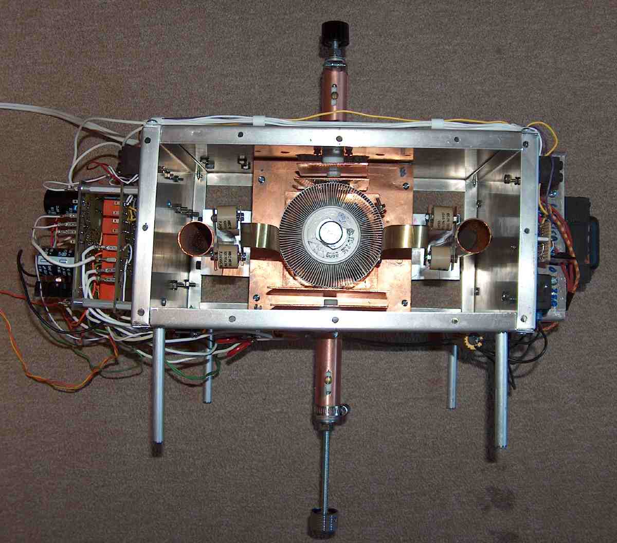
here for a top view of the
rf deck in a later stage of assembly, with the GS23B in place to align the output tank components.
The blower is attached on the back panel just below the load capacitor mount. I thought I had measured
everything carefully, but discovered some interference between the load cap actuator mounting plate and the blower flange
after all the holes has been drilled.
I fixed this by trimming the blower with a nibbling tool and file. It's a little ugly and made me angry at the time,
but nobody can see it.
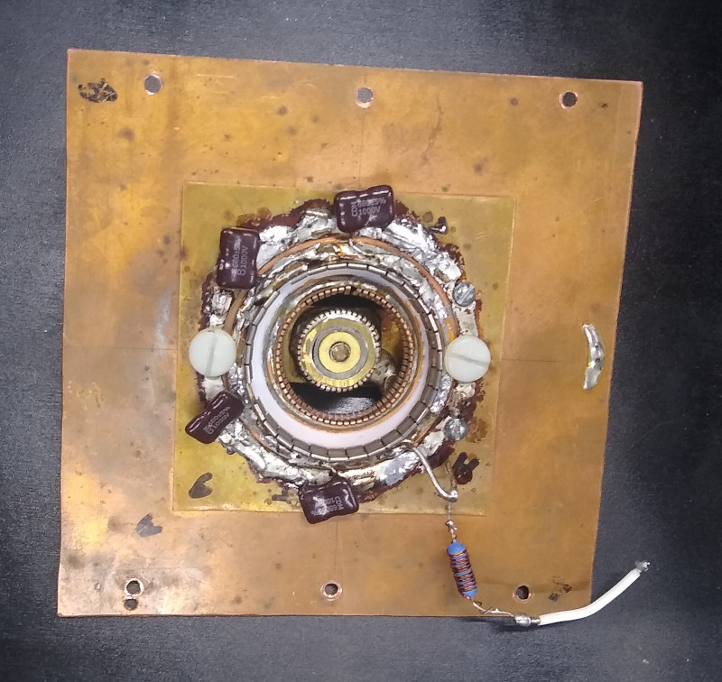
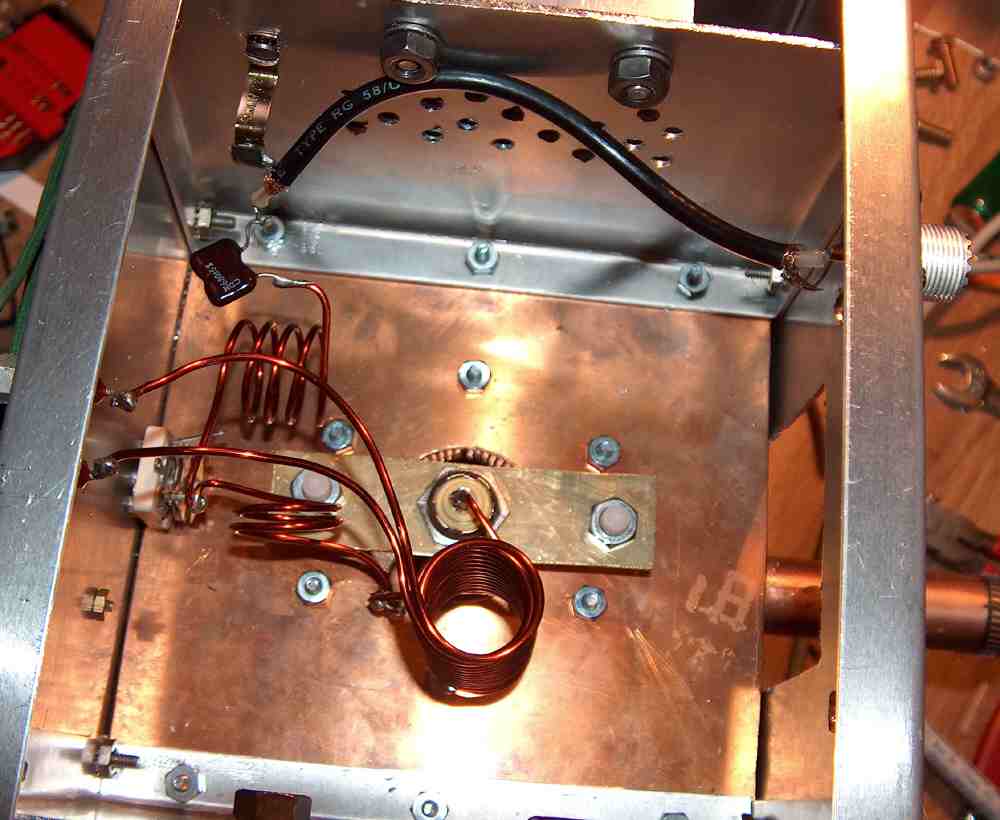
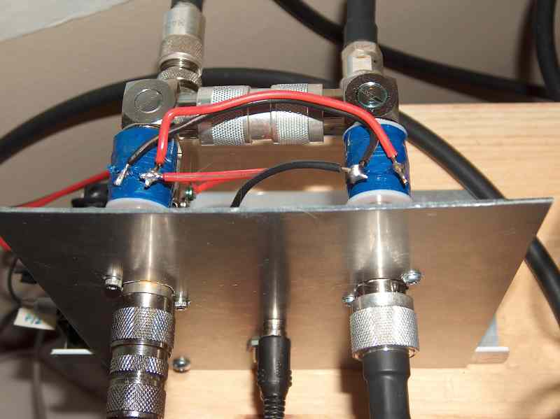
Flipping over
the rf deck shows details of the cathode compartment and the bottom of the tube socket.
The air-variable capacitor at left is tuned to match the transceiver to the amplifier, as described in the rf
testing section.
The amplifier is made robust and reliable with a pair of circuit boards designed by G3SEK. I bought
mine as a kit from Tom's Tubes (SK). The only
option I'm aware of for obtaining the tetrode boards now is to build them from scratch. Screen current is a excellent
measure of proper amplifier operation -- one of the boards' functions is to carefully watch this current.
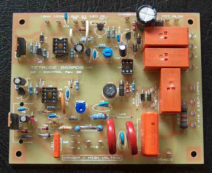
If it gets out of range that means there is a problem and the amplifier will be quickly shut down, hopefully saving expensive parts. Click
here
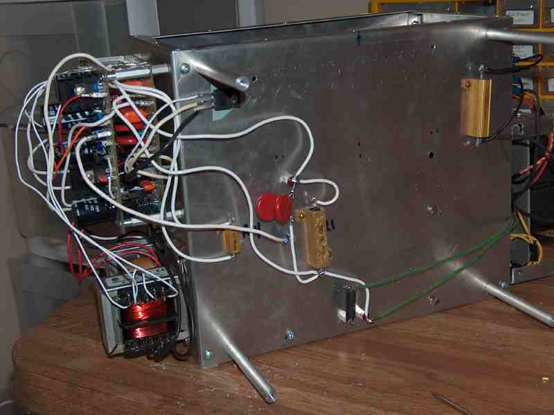
to see one of my boards after most of the components have been soldered in. Following KD5HIO, I stacked the boards
on one side of the rf deck as can be seen here. Below the boards are two transformers
for the control grid supply and the 12 Vdc supply. The two red disks are
protection MOV's. I connected
them in parallel from the screen grid feedthrough to the cathode in an effort to shunt
a voltage spike that would accompany
an accidental anode flashover. The MOV's are in series with a small rf choke on the screen ring, which slows down
the response time. Bypassing the choke, however,
would run the risk of placing rf on the cathode. Also visible
are the 6.3 VAC filament feedthroughs,
the screen regulation transistor (Q2), and power resistors that have been heat-sunk to the chassis.
Both the ALC and control grid current trip on the tetrode boards are disabled in this design. The boards also have
provision for relay sequencing to perform user configurable switching external to the amplifier. I did not use this
capability because I have a commercial sequencer from LNA Technology (presumably no longer in operation).
The sequencer routes the PTT command from the transceiver to switch out the tower-mounted preamp
while simultaneously activating the amplifier
and its power handling coaxial relays.
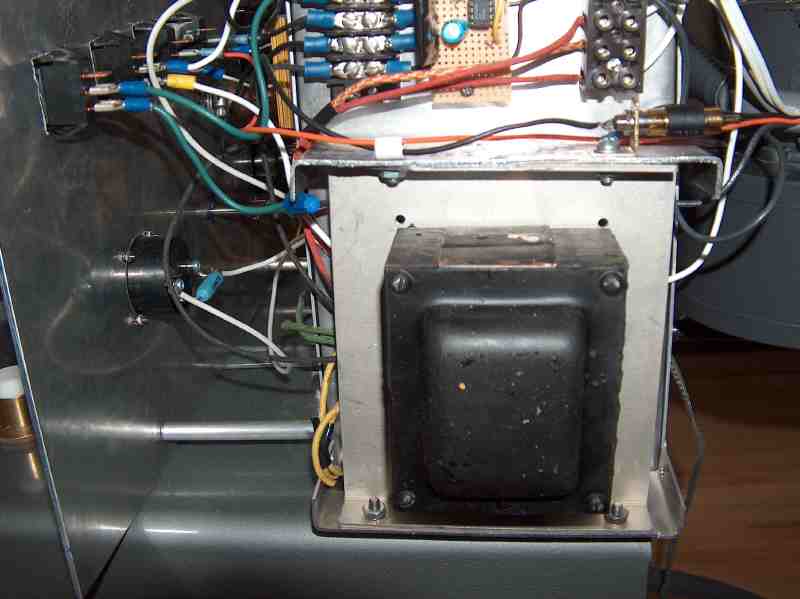
At the time I started assembling the rf deck, the recommended transformer for the screen supply was out-of-stock
at rfparts.com. I scoured ebay for alternatives and came up with an old heavy-duty Stancor transformer
with a secondary rated for 540 VAC at
280 mA. The design calls for 600 VDC and 40 mA, so this looked like
an excellent substitute. The screen supply could be regulated
down to 600 Volts and the hefty secondary current available meant the transformer would be barely working
in this application, a nice over-design.
Another bonus was a second winding that provided the 6.3 VAC filament bias at 10 amps -- that
meant I would not need a separate filament transformer. I snagged it for $49, shipped. A downside
of this transformer, which I
discovered after it arrived, was the absence of suitable mounting holes. N5XZM fabricated a custom bracket that
attached it to the other side of the rf deck. Regrettably, this
transformer did not work out; details are on the next page.
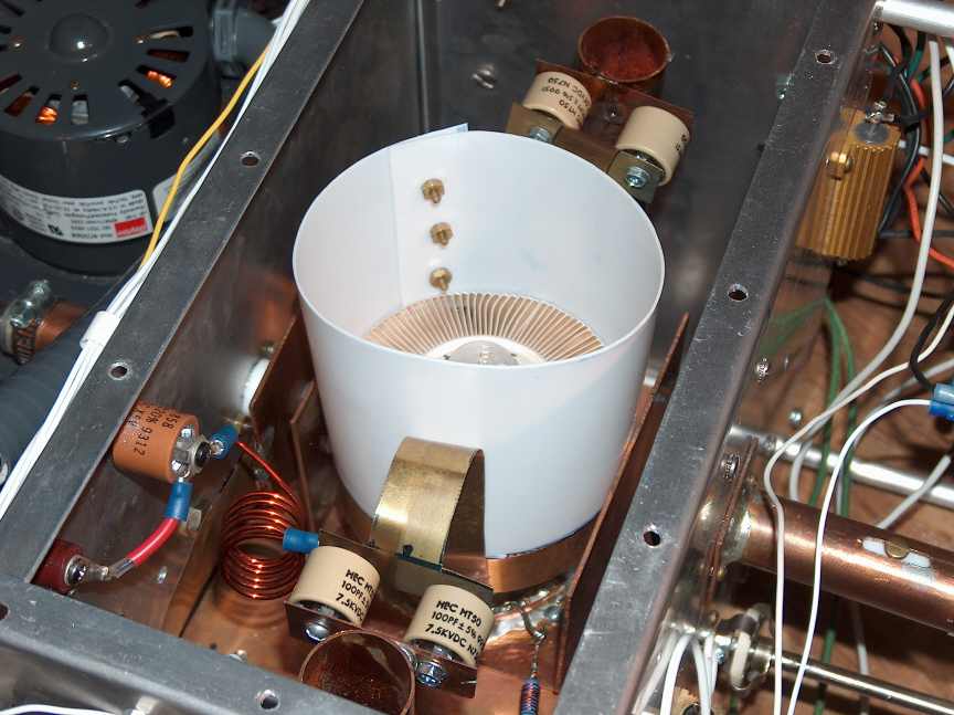
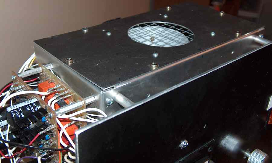
This photo shows the teflon chimney on the tube with mechanical construction of the rf deck
essentially complete. The cover is attached with simple sheet metal screws. A piece of hardware
cloth keeps rf from leaking out the vent hole that was cut using a drillpress and flycutter.
Hardware cloth is placed at the blower inlet for the same reason.
Meter faces were re-worked
using the software found here. Professional looking
custom switch and knob labels for the front panel were purchased from
Plastic-Tags (no longer in operation)
for about $25 shipped.
Part II: DC testing
WB2FKO homepage