The recommended screen transformer is specified with a 550 VAC secondary while my
Stancor substitute was rated at 540 VAC.
This would suggest a difference of little consequence. The voltmeter revealed otherwise. The measured output
voltage on my old Stancor was
right-on while the newer one in the KD5HIO setup showed a secondary voltage of 490 VAC, ie. much lower than spec.
This meant the
unregulated dc level from my screen supply came in at 767 Volts -- uncomfortably close to the maximum rating
of the electrolytic filter capacitors on the board. In addition, my screen supply would not properly regulate,
which prevented realization of the desired bias level of 600 Vdc. This was fixed by changing resistors R13 and R14
using
the Excel spreadsheet on the G3SEK design page.
This would have been an adequate workaround provided the screen transformer primary stayed
plugged into a 120 VAC wall outlet.
The rf deck, however, is fed 120 VAC from a 220/110 stepdown transformer located in the power supply cabinet. This
generated slightly higher input voltage that pushed the unregulated screen supply output to 820 Vdc, i.e. past the filter
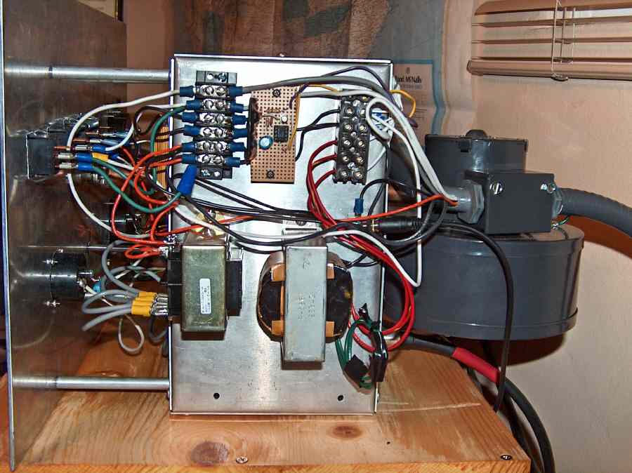
capacitor rating. I mulled over a few options and decided to swap out the big Stancor for the same screen transformer that
KD5HIO used, as it had since become available at rfparts.com. A separate filament transformer was also necessary.
You can see this pair of transformers installed where the big screen transformer used to be.
It may have been smarter and cheaper to keep the transformer and replace the caps,
but I wasn't sure I'd be able to fit bigger ones
in the existing space on the tetrode boards.
AC voltage should be applied to the filament with a step-start circuit. This is accomplished in essentially the
same manner as
is done with the main high voltage transformer. A 30-ohm power resistor is placed in one leg of the filament
transformer primary. A 555-timer circuit bypasses this resistor after a 4-second delay using a small solid-state relay.
This circuit is visible in the above photo on the perfboard. In the middle right is the PTT enable line from the
sequencer.
There are four SPST switches on the front panel for the blower, filament
heater, plate voltage enable, and PTT. The latter two are not
essential, but I couldn't imagine testing and tuning without them. Note
that the operator cannot apply plate voltage until the cathode has been
sufficiently warmed; a 4-minute delay for this purpose is enforced by a
timer on the tetrode boards.
Power dissipation at the screen electrode must be kept within the tube rating; the design calls for
no more than 20 mA at 600 Volts bias. The tetrode boards will shut down the amplifier if Ig2 exceeds a user-specified
setpoint. I played it conservative and decided on a screen current trip of
± 18 mA, ie. with current flowing in
either direction.
The setpoint is adjusted with a 500 ohm trimpot (RV2) on the control board that develops a voltage across the
gate of SCR Q3. When the gate threshold is exceeded, the SCR conducts
and immediately removes screen and anode voltage from the
tetrode. I was unable to generate enough
gate voltage to get a trip at Ig2 = 18 mA. This was solved be replacing RV2 with the 1k trimpot (RV101) that was part of
the disabled ALC and
grid current trip circuitry on the other board. It is a drop-in replacement.
After the boards are properly set, the next step is to plug the tube in the socket and see how it behaves.
A surplus Russian tube will have been sitting idle for the better part of two decades and must be re-conditioned.
There
are elaborate procedures for doing this,
but I chose to only run the filament (with blower on) for about 12 hours.
Further dc testing requires the presence of anode voltage. If the anode is off, enabling screen
bias with the PTT command will send way too much current into the screen and fire the trip.
So without the big power supply on, you are forcing the screen electrode to be the plate and that is not good!
At roughly 3700 Vdc on the anode I got 400 mA of current.
This is too high for the intended Class AB2 operation although it might be OK for Class A. Reduction of
plate current is addressed by making the control grid bias less positive. The KD5HIO amplifier runs 120 mA
with Vg1 at -47 Vdc, but my tube was clearly not responding the same way.
I needed to go more negative than -47 V.
The control grid bias is adjusted by replacing the Zener diode reference voltage in the
power supply circuit on the tetrode board.
I had to do some scrounging on ebay for incremental values of 1N53XX series Zener diodes and eventually
hit 100 mA of idle plate current (no rf drive) at a grid-cathode bias of -63 Vdc.
This bias voltage was a significant deviation
from the KD5HIO design and should have tipped me off that our GS23B tetrodes were very different.
Note that 1N53XX Zener diodes are obsolete; more expensive substitutes are available at Mouser.
The protracted process of dialing-in
the plate bias current provided me with a large collection of Zener diodes in the range 47--64 Volts.
Part III: RF testing
WB2FKO homepage