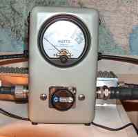
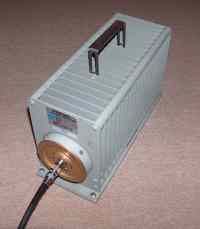
The equipment needed to tune the amplifier is minimal. I used the 600
Watt dummy load shown above, a Bird 43 Wattmeter with a 2.5 kW slug
covering 100-250 MHz, the built-in SWR meter on the Icom-746Pro
transceiver, and the three panel meters on the rf deck for plate
current, screen current, and control grid current.
I let the WSJT program control rf testing: I arbitrarily selected one of
the four FSK tones for USB and set the sequence for a 30 second on-off
cycle as is the usual practice for meteor scatter operation. The first
step is to get a good SWR between transceiver and rf deck. The
transceiver must key PTT on the amplifier and all bias voltages must be
in place, including the anode. This may seem obvious but it wasn't to
me at the time. In my setup, the match between transceiver and
amplifier shows a very sharp resonance.
In the initial search for power gain, I throttled back the transceiver to
its minimum output of 5 Watts. A 250 Watt slug was put in the inline
wattmeter for increased sensitivity. The standard procedure for tuning
a W6PO triode amplifier is to systematically vary the tune and load
capacitors while watching the wattmeter. This should guide you toward
resonance. When rf was applied the plate current jumped, which was a healthy sign.
I was properly driving the tetrode but not yet seeing any gain.
Highest power meter deflection occurred
at maximum capacitor separation, which indicated I had too much tune and load capacitance
(C5, C6, respectively) available. I addressed the latter by shortening the inductor pipes in
the output tank (L5, L6) by loosening their clamps and pushing them as
far down into the chassis as possible. This helped a little, so the
next step was to physically shorten them by sawing off 1/4 inch each.
This gave me a minimal amount of rf gain, but it was clear I was still
way off resonance. I removed another 1/4 inch from each pipe and
observed about 13 dB gain. I reduced plate tank inductance even more by shortening
the straps that connect the pipes to the anode clamp. The tune capacitor responded accordingly,
but it would not make any more power. The amplifier wanted lighter loading and I was at maximum capacitor
separation at C6.
The next logical step was to reduce the load capacitance area. This was implemented by progressively
snipping corners
from the capacitor plates. With each reduction in capacitor area, incremental power increases
were obtained. I took this to the limit by completely removing the plate attached to the anode ring.
The amplifier was now pushing about 200 Watts with 5 Watts drive, but all the modifications
to the load capacitor had made it difficult to
achieve resonance on the tune side of the circuit. The output power was not stable and I also started getting
rf arcs that would usually (but not always) trip the screen current shutdown.
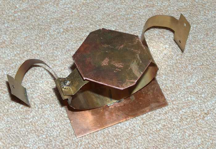
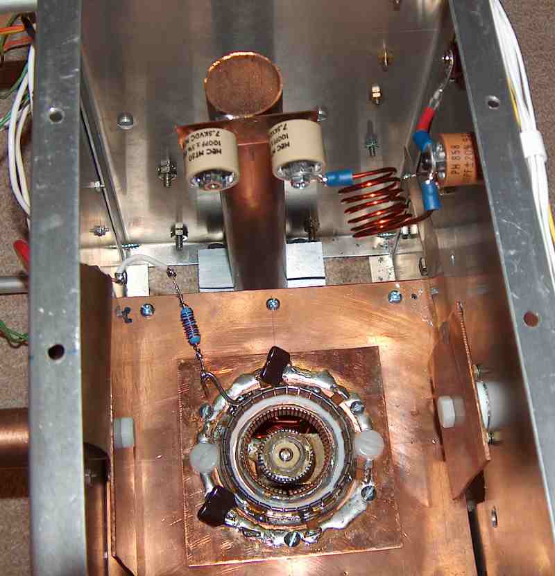
RF arcs are notoriously difficult to locate, but not in this case.
I could always trace them to one of the two nylon 1/4-20 screws retaining the
moveable capacitor plates to their teflon shafts.
Both nylon screw heads are visible in this top view with the GS23B removed.
The pitted
plastic revealed the presence of an rf arc. I assumed the screws were high field
points that served to initiate arcs, presumably because the plates were too close together.
Adjusting the inductor lengths could achieve resonance at higher plate separation, but arcing
invariably occurred when the power level exceeded 200 Watts.
To further complicate things,
the SWR read by the transceiver would get progressively worse as amplifier power increased.
I was also concerned that the
amplifier just couldn't be loaded lightly enough.
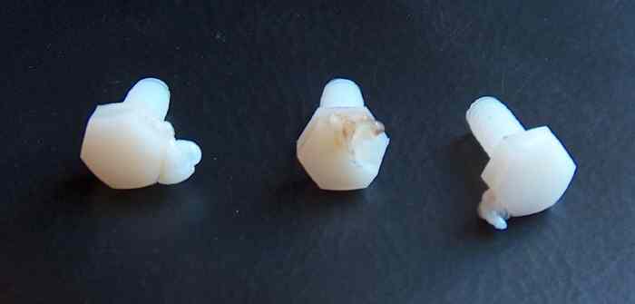
After toasting almost a dozen nylon screws, it hit me that the issue was not
high-field dielectric breakdown
but excessive heat in the screws. In one case I saw that nylon had dripped down the copper capacitor
plate like candle wax.
This explained the power instability on the wattmeter and fluctuating screen current. The
melting problem was
solved with (expensive) teflon screws that I purchased from McMaster-Carr.
I also realized that plate load resistance
is a function of plate current. The capacitor dimensions were
calculated assuming the tube
was carrying more than 800 mA at 1.5 kW output, not 200 mA where I was trying to tune. The amplifier started
to respond favorably to load adjustments when the drive power increased to 10 Watts with
a concomitant jump in plate current. A new capacitor plate
was attached to the anode ring to replace the one I had chopped up trying to make the amplifier work at 5 Watts
input. For this reason, I do not drive the amplifier with less than 15 Watts. I'm sure
the circuit can be tweaked to
provide enough dynamic range for efficient operation between 0--30 Watts drive, but the way I have it now is
adequate for my use.
A tetrode amplifier tunes with a distinctly different
procedure than a triode; it must be re-adjusted for each drive level. Lightening the load
causes the screen current to increase along with the rf power. It also increases the plate voltage swing,
which can result in rf arcing. The load capacitor is set to control the screen current, not the
output power. The goal in tetrode amplifier adjustment is to set the load capacitance
for optimum or recommended screen current.
This current is likely to be an empirical, approximate value that trades-off gain, distortion, and propensity for rf arcing.
A triode
amplifier, in contrast, only requires the operator to adjust the tune and load
capacitors for maximum output power.
My procedure is as follows: Arbitrarily set the load
capacitance (C6). Apply rf and check for good SWR; this rarely needs adjustment. Adjust the tune capacitor (C5)
to maximize the screen current while watching the control grid current (plate current
is not affected by tuning). Try another value of C6 and peak with C5. As resonance is approached, screen current (Ig2)
will first go negative and then swing positive. For a given load, maximum screen current gives maximum rf power.
I also see control grid current (Ig1) become negative as the output power cranks up. This alarmed me at first because
it was inconsistent with the operation of KD5HIO's amplifier
where Ig1 is always positive. I re-checked and re-calibrated the meter to make sure
it was properly wired and determined everything was OK. Then it dawned on me that
negative Ig1 is qualitatively consistent with K5GW's 432 MHz GS23B
amplifier. The upshot is there exists
enough variation between individual tubes to significantly affect the operating characteristics.
I would not expect my amplifier to perform the same way if a different GS23B were substituted.
The screen and control grid currents (Ig2 and Ig1) listed on the
first page are approximate.
Lightening
the plate load (ie. decreasing C6) will cause a slight increase
in power, but will also dramatically increase Ig2
and force Ig1 even more negative when C5 is brought into resonance.
I stop reducing C6 when Ig1 gets to -4 mA and leave it at that.