| GS23B Tetrode Amplifier Project |
|
Hansen's Laws:
1) You can never have too much power available. 2) You build amplifiers to make power, not to admire. -- KD5HIO, Amplifier Designer |
|
| Published online in 2007; updated in 2023.
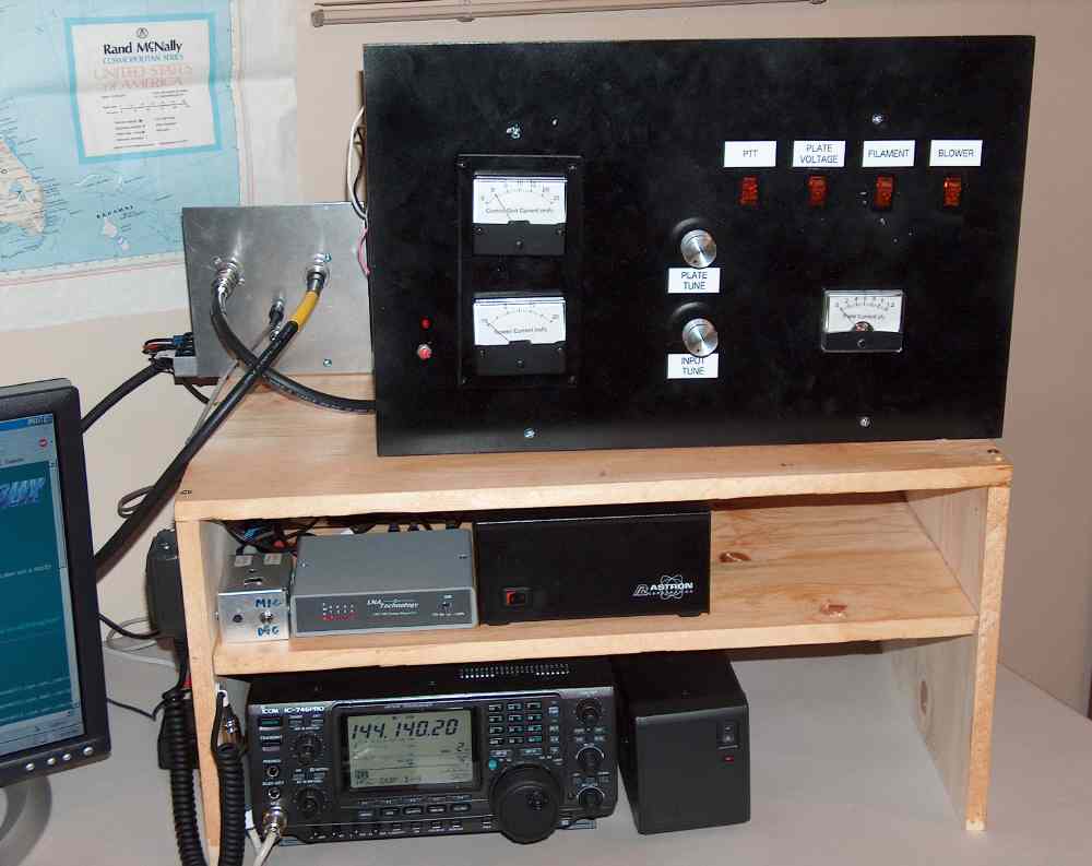
The following pages describe my home-built 144 MHz power amplifier. It essentially duplicates the amplifier that was designed and built by Glen Hansen, KD5HIO. A detailed technical write-up of the amplifier with parts list and construction details can be found here. The design is based on a surplus Russian GS23B (Svetlana 4CX1600U) tetrode. Click here for an English translation of the operating manual that came with my tube. This was my first QRO project and it was a challenge. I am not much of a machinist or mechanical tinkerer, so successful completion of this amplifier required a lot of patient help from KD5HIO (mostly via email) and some parts fabrication courtesy of my friendly neighbor Bob, N5XZM (SK). Here I describe many of the construction, testing, and tuning details that are not covered in KD5HIO's original article on the ND2X QRO page. The nominal operating parameters I get are as follows, testing with a Bird 43 Wattmeter into a 50 ohm dummy load: |
|||||||||||||||||||||||||||||||||||||||||||||||
|
|||||||||||||||||||||||||||||||||||||||||||||||
| The output drops several percent when a low-pass filter is in place. This is due to
insertion loss and reduction of out of band harmonics the amplifier is producing. More about operation and tuning
can be found in the link below.
Total time for the project, which started with the installation of Romex line for 220 VAC under the house to the first completed QSO via FSK441a meteor scatter, was 3 years and 3 months. That was much longer than I anticipated, but I certainly did not work on it continuously during that span. Professional obligations, travel, and other distractions kept me from it for months at a stretch. That said, I have many, many hundreds of hours invested. Knowing what I know now, I'm pretty confident I could build a second one in under a year, working on it no more than an hour each day. How much did it cost? That's the first thing people usually ask. I kept track of all (or almost all) the parts on a spreadsheet, including shipping fees. Included in the tally is the high voltage power supply, which I also built myself, a high power dummy load, coaxial relays, a high power slug for the power meter, and a high power low-pass filter. Many of the expensive components are ancillary to the rf deck, but I include them because they reflect the overall financial commitment one must make after deciding to go QRO. Total cost came in at about $3,100 (circa 2005-7 prices). The big ticket items are, in descending order:
|
|||||||||||||||||||||||||||||||||||||||||||||||
|
|||||||||||||||||||||||||||||||||||||||||||||||
| WB2FKO homepage |